Structured Cabling and Data Points Guide to Building an Efficient Network Rack
- Valenty Buranda
- Aug 20
- 10 min read

A messy network rack usually starts as one small shortcut. A cable is run without a label. A patch lead is left too long. A data point is added without updating the schedule. Months later, a simple fault takes an hour to trace because nobody can tell where anything goes.
Structured cabling prevents that slow slide into chaos. It gives a network a planned physical layout, so computers, access points, printers, phones, cameras, servers and other devices can connect cleanly and reliably. Good switching and routing matter, but they sit on top of the cabling layer. If that layer is poorly built, the whole network feels harder to manage.
This guide explains the main parts of a structured cabling system, how data points fit into the design, and how to build a rack that stays organised after the installation team leaves.

Structured cabling is the physical map of the network
Structured cabling is a planned system of fixed cables, outlets, patch panels, racks and cable management hardware. Instead of running random point-to-point cables from one device to another, the cabling follows a repeatable pattern.
A common setup looks like this:
A data point in a room connects to a fixed cable inside the wall or ceiling.
That cable runs back to a communications rack.
The cable terminates on a patch panel.
A short patch lead connects the patch panel port to a network switch.
The switch connects that device to the wider network.
This design separates the permanent cabling from the active equipment. The fixed cable can stay in place for many years, while switches, routers and wireless controllers can be replaced or reconfigured as needs change.
The benefits are practical:
Faults are easier to trace because each outlet has a matching patch panel port.
Moves and changes can happen at the rack, not inside walls.
Equipment is easier to replace without touching fixed cabling.
Labelling and documentation reduce guesswork.
The network can grow without becoming tangled.
Structured cabling also supports different services over the same type of cabling. One outlet might serve a desktop computer today, a wireless access point next year, and a VoIP phone after that. The cabling does not care, as long as the installed cable, connectors and devices support the required speed and power.
For Australian sites, installers often refer to standards such as AS/NZS 3080, ISO/IEC 11801 and related cabling rules. The exact requirements depend on the site, but the principle is the same: use recognised cable categories, correct termination methods, safe pathways and proper testing.
The key components that hold the system together
A structured cabling system is only as strong as its parts and the way they are installed. The main components are simple, but each one has a clear job.
Cables carry the signal
Twisted-pair copper cable is the common choice for local area networks. You will often see Category 6 or Category 6A cable in modern installations. Both use pairs of copper conductors twisted together to reduce interference. Category 6A is designed for higher performance over longer runs at 10 gigabit speeds, while Category 6 suits many standard business and home networks.
Fibre optic cable is used where higher bandwidth, longer distances or electrical isolation are needed. It is common for connections between racks, between buildings, or back to a main equipment room.
When choosing cable, think about:
The speed needed now and over the next few years
Cable distance between outlet and rack
Pathways near power cables or noisy electrical equipment
Power over Ethernet needs for devices such as access points and cameras
Fire rating and installation environment
The cheapest cable is rarely the lowest-cost choice if it needs to be replaced early.
Connectors finish the cable ends
Connectors and jacks create the physical interface between cable and equipment. In copper networks, fixed cabling usually terminates into keystone jacks at the outlet and IDC-style terminations at the patch panel. Patch leads then use RJ45 plugs to connect devices.
Good termination matters. Untwisting pairs too far, damaging conductors, or mixing wiring schemes can create faults that are hard to see but easy to feel. The network may connect, but performance can drop, especially under load.
Use one wiring scheme consistently, such as T568A or T568B, based on the site standard. The main point is consistency from end to end.
Patch panels create a clear handover point
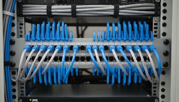
A patch panel is the control surface for the fixed cabling. Each rear termination connects to a cable that runs to a data point. Each front port accepts a patch lead that connects to a switch or other equipment.
Patch panels make the rack readable. Instead of a hundred wall cables disappearing straight into switches, the fixed cabling lands in one ordered row of ports. That gives technicians a clear place to test, patch, isolate and document connections.
A good patch panel layout should match the data point schedule. For example, ports 1 to 24 might serve the ground floor, while ports 25 to 48 serve the first floor. If the patch panel numbering matches the outlet labels, support work becomes much faster.
Data points need planning, not guesswork
A data point is the user-facing end of the cabling system. It may be a wall outlet, ceiling outlet, floor box, or other fixed connection point. It looks simple, but poor planning here can cause years of frustration.
Start by mapping where connected devices will actually live. Include:
Workstations and docking stations
Printers and scanners
Wireless access points
IP phones
Security cameras
Smart TVs and meeting displays
Point-of-sale devices
Building systems and controllers
Spare ports for growth
Wireless networks still need cabling. Every access point usually needs a data point, often with Power over Ethernet. Camera systems, door controllers and other smart devices also depend on well-placed outlets.
A useful rule is to install more data points than the bare minimum. Empty ports in a wall plate are cheaper than opening walls later. That does not mean filling every surface with outlets, but it does mean planning for likely changes.
Label data points in a way people can follow
Labels should connect three things:
The physical outlet
The patch panel port
The documentation
A label such as `G.012-A` might mean ground floor, outlet 12, port A. Another site might use room numbers, such as `RM14-01`. The exact format matters less than clear, consistent use.
Avoid labels that depend on the current user or device, such as `Accounts Printer`. Devices move. Cabling should be tied to locations and ports.
A simple data point schedule can include:
Field | Example | Why it helps |
Outlet label | `L1-023-A` | Matches the wall plate |
Patch panel port | `PP1-23` | Shows where it appears in the rack |
Room or area | Training room | Helps locate the outlet |
Service | Data, voice, WAP, CCTV | Shows intended use |
Switch port | `SW1-17` | Helps with fault tracing |
Test result | Pass | Confirms the cable was tested |
Keep this document somewhere the support team can access. A printed copy in the rack door can help during urgent work, but a maintained digital version is better for long-term control.
Build the rack around access, airflow and change
A network rack should make equipment easy to reach, cables easy to follow and airflow easy to maintain. A tidy rack is not just about appearance. It reduces downtime and makes upgrades easier.
Choose the right rack size
Start with the expected equipment list:
Patch panels
Network switches
Router or firewall
Fibre trays or enclosures
Cable managers
Power rails
UPS
Shelves for non-rack equipment
Future expansion space
Rack space is measured in rack units, or `RU`. One rack unit is 44.45 mm high. A 24-port patch panel is often 1RU, and many switches are also 1RU. That sounds simple, but cable managers, blanking panels and airflow space also take room.
Do not fill the rack to 100 per cent on day one. Leave space for future switches, extra patch panels and better cable routing. A rack that starts full will become untidy fast.
Place equipment in a logical order
There is no single layout that suits every site, but a sensible rack order often places patch panels near switches. This keeps patch leads short and readable.
One common layout is:
Horizontal cable manager
Patch panel
Horizontal cable manager
Network switch
Repeat as needed
This pattern lets patch leads travel short distances without crossing the whole rack. It also makes it easier to replace a switch without disturbing fixed cabling.
Keep heavier equipment, such as UPS units, low in the rack. This improves stability and makes the rack safer to work around. Keep equipment that needs regular access at a comfortable height where possible.
Manage vertical and horizontal cable paths
Use horizontal cable managers between patch panels and switches. Use vertical cable managers along the side of the rack for larger cable bundles. Velcro-style cable ties are usually better than plastic zip ties because they can be reopened and are less likely to crush cables.
Avoid tight bends. Copper and fibre cables both have bend radius limits. If a cable is bent too sharply, it can pass a basic visual check but fail performance testing.
Also avoid packing cables so tightly that they block fans or vents. Switches need airflow. If heat builds up, equipment life and network stability can suffer.

Patch with purpose instead of creating cable clutter
Patch leads are easy to overlook because they are small and cheap compared with switches and racks. They also create most visible rack clutter.
Use the right length. A 300 mm or 500 mm lead might suit patching between adjacent rows. Longer leads are useful when equipment sits further apart, but extra length should be routed through cable management, not looped across ports.
Colour coding can help, as long as the scheme stays simple. For example:
Blue for general data
Yellow for wireless access points
Green for voice
Red for critical links
Purple for cameras
Document the colour scheme and stick to it. Too many colours without rules can be worse than no colour coding at all.
For higher-speed links, use patch leads that match the installed cabling category. A Category 6A permanent link should use suitable Category 6A patch leads if the aim is to support that performance end to end.
A neat rack is useful only if it stays neat after changes. Make every patch easy to remove, trace and document.
Testing proves the cabling works
A cable can look perfect and still fail. Testing confirms that the installed cabling meets the required performance level.
Basic continuity testers can find simple faults such as open pairs, shorts and crossed wires. Certification testers go further and measure performance against a cabling standard. For commercial installations, certified test results are often expected because they give proof that each permanent link meets the design target.
Common faults include:
Split pairs
Poor termination
Damaged cable jackets
Excessive cable length
Tight bends
Mixed components from different categories
Interference from poor pathways
Testing should happen before the site depends on the network. Fixing cabling faults after furniture, ceilings and business systems are in place is slower and more disruptive.
Efficient data flow starts with the physical layer
Data flow is often discussed in terms of switches, VLANs, routing and internet links. Those layers matter, but the physical layer comes first. If cabling is unreliable, the network may show intermittent faults that look like software or hardware issues.
To support efficient data flow, focus on these habits:
Match device needs to port capacity
High-demand devices, such as wireless access points, servers, uplinks and video systems, may need faster switch ports or dedicated uplinks. Do not treat every port as equal if the traffic patterns are different.
Keep uplinks clear and planned
Switch uplinks should be easy to identify. Label them clearly and avoid mixing them with general patching. If a switch connects back to a core switch or router, that link deserves careful documentation.
Use Power over Ethernet with care
PoE is useful for access points, cameras and phones, but switches have power budgets. A port may support PoE, but the switch still has a total limit. Plan the load before adding many powered devices.
Separate services where needed
Some networks use VLANs to separate data, voice, cameras, guest Wi-Fi and building systems. The cabling does not create VLANs by itself, but clear labelling helps technicians patch and support those services correctly.
Remove abandoned patch leads
Old patch leads create confusion. If a device is removed, update the data point schedule and remove the patch lead unless the port needs to remain active.

A simple rack build process that works
A good rack build follows a clear sequence. Skipping around often leads to rework.
Confirm the design
Check the number of data points, cable categories, rack size, switch count, PoE needs and future capacity.
Plan cable entry
Decide whether cables enter from above, below or both. Protect cables from sharp edges and keep pathways tidy from the start.
Mount passive hardware
Install patch panels, fibre enclosures, cable managers and blanking panels before active equipment where practical.
Terminate and dress fixed cabling
Bring cables to the patch panels in ordered bundles. Keep labels visible and avoid pulling cables tight.
Install active equipment
Mount switches, routers, firewalls and UPS equipment in logical positions. Keep heavy devices low.
Patch in short, readable paths
Use suitable patch lead lengths and route them through managers. Do not run diagonal shortcuts across the rack.
Test and document
Test each link, record results and update the data point schedule. Photograph the finished rack for reference.
Set rules for future changes
Decide who can patch, who updates records and how unused ports are handled.
The last step matters more than many teams expect. A rack can be installed beautifully and still become messy if every change happens under time pressure with no process.
Common mistakes that make racks harder to support
Most rack problems are avoidable. Watch for these habits:
Running fixed cabling straight into switches instead of patch panels
Using patch leads that are far longer than needed
Leaving ports unlabelled
Mixing old and new cable categories without checking performance needs
Blocking switch airflow with cable bundles
Failing to document data point changes
Ignoring spare capacity
Using tight zip ties that damage cable bundles
Placing UPS units too high in the rack
Forgetting to test every link
These mistakes may not break the network on day one. They usually show up later, when someone needs to troubleshoot under pressure.
Good cabling pays off every time the network changes
Structured cabling is not the most visible part of a network, but it affects almost every support task that follows. A clear data point schedule, well-terminated cable, labelled patch panels and a carefully built rack make the network easier to run, easier to fault-find and easier to grow.
The best racks have a simple quality: someone new can open the door and understand the layout within minutes. That only happens when the physical design, labelling and documentation all tell the same story.
Plan the cabling before devices arrive. Build the rack for access, airflow and change. Treat data points as part of a managed system, not just sockets in a wall. The result is a network that feels calm to support, even as the number of connected devices keeps growing.



Comments